Attēls:PWM, 3-level.svg
Pāriet uz navigāciju
Pāriet uz meklēšanu

Size of this PNG preview of this SVG file: 688 × 475 pikseļi. Citi izmēri: 320 × 221 pikseļi | 640 × 442 pikseļi | 1 024 × 707 pikseļi | 1 280 × 884 pikseļi | 2 560 × 1 767 pikseļi.
Sākotnējais fails (SVG fails, definētais izmērs 688 × 475 pikseļi, faila izmērs: 18 KB)
Kopsavilkums
| Apraksts |
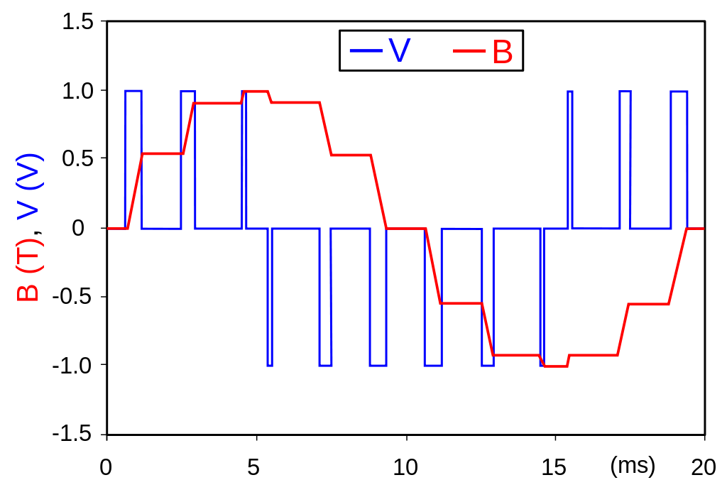
English: A simplified example of pulse-width modulated (PWM) voltage supply to a magnetic circuit. The voltage (blue waveform) in a magnetic circuit is proportional to the rate of change of the flux density (red waveform). Therefore, by using PWM supply the resultant flux density can be controlled with relative ease. This method is commonly used for supplying electric motors, in which the torque is proportional to the flux density. As can be seen, with a series of appropriately modulated voltage impulses the resultant flux density can be modulated to be close to desired sinusoidal waveform. In the example shown (for 50 Hz), for clarity the switching frequency is 600 Hz, in real devices the switching frequency is much higher - even up to 10 kHz or higher. Of course, for higher fundamental frequency the switching frequencies would be even higher.
Polski: Przykładowe przedstawienie modulacji szerokości impulsu (PWM) dla obwodu magnetycznego. Napięcie elektryczne (niebieski przebieg) w obwodzie magnetycznym jest proporcjonalne do szybkości zmian indukcji magnetycznej (czerwony przebieg). Dlatego też, poprzez użycie PWM wypadkowa indukcja magnetyczna może być kształtowana z względną łatwością. Metoda ta jest szeroko stosowana do zasilania i kontrolowania pracy silników elektrycznych, w których moment obrotowy na wale silnika jest proporcjonalny do indukcji magnetycznej. Jak widać na rysunku, wypadkowa indukcja (dąży się zazwyczaj do kształtu sinusoidalnego) może być łatwo kształtowana poprzez użycie odpowiednio modulowanych impulsów. W pokazanym przykładzie (dla 50 Hz), dla jasności rysunku użyto częstotliwość przełączania 600 Hz. W rzeczywistości jednak stosuje się znacznie większe częstotliwości przełączania - nawet do 10 kHz lub więcej. Oczywiście dla nośnych częstotliwości wyższych niż 50 Hz częstotliwości przełączania będą znacznie większe. |
| Datums | |
| Avots | Paša darbs |
| Autors | Zureks |
| SVG veidošana |
Licence
Es, šī darba autortiesību īpašnieks, publicēju to saskaņā ar šīm licencēm:

|
Ir dota atļauja kopēt, izplatīt un/vai pārveidot šo dokumentu saskaņā ar GNU brīvās dokumentācijas licences, versijas 1.2 vai jebkuras vēlākas versijas, ko publiskojis Brīvās programmatūras fonds nosacījumiem; bez nemainīgajām sadaļā, priekšējā un aizmugurēja'vāka tekstiem. Licences kopija ir iekļauta sadaļā ar nosaukumu GNU brīvās dokumentācijas licence. |
| Šis fails tiek izplatīts saskaņā ar licences Creative Commons Atsauce-Līdzīgi Noteikumi 3.0 Vispārējiem noteikumiem. | ||
| ||
| This licensing tag was added to this file as part of the GFDL licensing update. |
This file is licensed under the Creative Commons Attribution-Share Alike 2.5 Generic, 2.0 Generic and 1.0 Generic license.
- Jūs varat brīvi:
- koplietot – kopēt, izplatīt un pārraidīt darbu
- remiksēt – pielāgot darbu
- Saskaņā ar šādiem nosacījumiem:
- atsaucoties – Tev ir jānorāda autors, saite uz licenci un to, vai veiktas kādas izmaiņas. To var darīt jebkādā saprātīgā veidā, bet ne tādā, kas norādītu, ka licencētājs atbalsta tevi vai veidu, kā tu izmanto šo darbu.
- nemainot licenci – Ja tu miksē, pārveido vai izmanto materiālu, tev savs devums jāpublicē ar to pašu vai saderīgu licenci kā oriģināls.
Jūs varat izvēlēties licenci pēc jūsu vēlmes.
Faila hronoloģija
Uzklikšķini uz datums/laiks kolonnā esošās saites, lai apskatītos, kā šis fails izskatījās tad.
| Datums/Laiks | Attēls | Izmēri | Dalībnieks | Komentārs | |
|---|---|---|---|---|---|
| tagadējais | 2007. gada 24. marts, plkst. 21.36 | | 688 × 475 (18 KB) | wikimediacommons>Zureks | {{Information |Description=An example of pulse-width modulated voltage supply to a magnetic circuit. The voltage (blue waveform) in a magnetic circuit is proportional to the rate of change of the flux density (red waveform). Therefore, by using PWM suppl |
Faila lietojums
Šo failu izmanto šajā 1 lapā: